Gesture control for PowerPoint presentation

Basic idea of the project

The intention of this tutorial is to learn how to control computer keyboard and mouse events using your micro-controller. For demonstration I have chosen to name the project as gesture control for PowerPoint presentation. At the end of this tutorial you will be able to control the slides using your gestures. Now in order to control the operating system you need a language like python, java, c++ etc. I find python affable and powerful so I’ll be using that for coding. You can use any language you want but the logic and algorithm will remain the same, only the syntax will differ. I won’t be teaching you python in this post that is beyond the scope of this post. If you want to learn the language there is plethora of content available online. You just need a net connection and off you go.
P.S. : If you like the posts do like and share them with others.

Python

Python is an easy to learn high level programming language. It is a beautiful and a very powerful language. The packages that are available make it kind of limitless. Some of the places where python is used are mentioned below.

  • Google makes extensive use of Python in its web search systems.
  • The popular YouTube video sharing service is largely written in Python.
  • The Dropbox storage service codes both its server and desktop client software primarily in Python.
  • The Raspberry Pi single-board computer promotes Python as its educational language.
  • NASA, Los Alamos, Fermilab, JPL, and others use Python for scientific programming tasks.

So we know that most of the big shots use python. Now they use it for a reason and the reason being that its simply an awesome language. If you want to start learning programming you ought to start with python. Here are a list of sites and books that you may use for learning python.

  1. https://www.python.org/about/gettingstarted/ (This is the official page where you can learn how to install the IDE and get started.)
  2. Learning Python, 5th Edition (This is a good book if you are new to programming and otherwise as well.)
  3. http://www.learnpython.org/
  4. http://www.tutorialspoint.com/python/

Once you get the hang of it then you can directly use the documentations for learning how to use the packages.

pySerial and PyUserInput

We will be requiring these modules in our project. The names are quite self explanatory the former is for serial communication while the latter is for the mouse and keyboard events. The links to these modules are:

Well download these and install them. I recommend you to use 32bit python 2.7 version modules as well as the language. Because most of the modules are available for 2.7 version.

Components and Software requirements

  • A microcontroller board with UART capability e.g. MSP430G2 Launchpad, Arduino Uno board etc.
  • An accelerometer e.g. ADXL335 etc..
  • Python 2.7 , pySerial & PyUserInput modules

Connections

connections

I have used fritzing for making this. Here is the link to their home page.  http://fritzing.org/home/

Logic

We will calibrate the accelerometer and take readings for left and right position. Use the serial monitor for this. Read my tutorial titled Capacitive Accelerometer Interfacing if you don’t know what I am talking about. Next once you have those digital values you need to make the program for slide control. We know that left arrow and right arrow keys are used for navigation purpose. So in our python script the if statements will contain code for left arrow button press and right arrow button press. Note that you are reading the values that the controller is sending serially using python and taking decisions based on that value.

Energia Code

int x_pin = A0;
void setup()
{
  // put your setup code here, to run once:
  Serial.begin(9600);
  pinMode(x_pin,INPUT);
  analogReference(INTERNAL2V5);
}

void loop()
{
  // put your main code here, to run repeatedly:
  int x = analogRead(x_pin);
  Serial.println(x);
  delay(500);
}

Python Script

__author__ = 'MANPREET'
'''
This is a file for controlling keyboard events.
'''
from pykeyboard import PyKeyboard
import serial
import time

comPort = raw_input("Please enter the COM port number")
baudRate = raw_input("Please enter the baud rate")
myserial = serial.Serial(comPort, baudRate)
k = PyKeyboard()
TRUE = 1;
try:
    while (TRUE):
        if (myserial.inWaiting()):
            mydata = myserial.readline()
            x = int(mydata)
            print(x)
            if x > 650:
                k.tap_key(k.left_key)
                print("left")
                time.sleep(1)
            if x < 550:
                k.tap_key(k.right_key)
                print("right")
                time.sleep(1)
except KeyboardInterrupt:
    print("stop")

Code Explanation

The Energia code is pretty straightforward but still just to cover that as well. We have declared A0 i.e. P1.0 pin as input and changed the ADC reference voltage to 2.5V in line 7. Next part is just getting the ADC reading and sending it serially.

The python code demands some explanation. So lets begin understanding the code .

from pykeyboard import PyKeyboard
import serial
import time

This code will import three modules PyKeyboard, serial and time. For the pykeyboard we have imported the constructor. Then you have made one object k using the same.

comPort = raw_input("Please enter the COM port number")
baudRate = raw_input("Please enter the baud rate")
myserial = serial.Serial(comPort, baudRate)
k = PyKeyboard()

myserial is an object of the serial module that you have imported. You will use this to access its functions. The raw_input() is for taking the com port and baud rate values from the user. Example COM11 and 9600.

TRUE = 1;
try:
    while (TRUE):
        if (myserial.inWaiting()):
            mydata = myserial.readline()
            x = int(mydata)
            print(x)
            if x > 650:
                k.tap_key(k.left_key)
                print("left")
                time.sleep(1)
            if x < 550:
                k.tap_key(k.right_key)
                print("right")
                time.sleep(1)
except KeyboardInterrupt:
    print("stop")

Well this is an infinite loop and you are checking this block for keyboard interrupt i.e. ctrl+c . This is done so that you can come out of the program properly without having to kill the program. Next we are checking if there is data in the serial buffer. If yes then we are storing it in mydata variable. Convert it into integer and store it as some variable say x. Next step is easy write two if statements and include the code and condition for left arrow button press and right arrow button press. For more details of the PyKeyboard module visit : https://pypi.python.org/pypi/PyUserInput/0.1.9
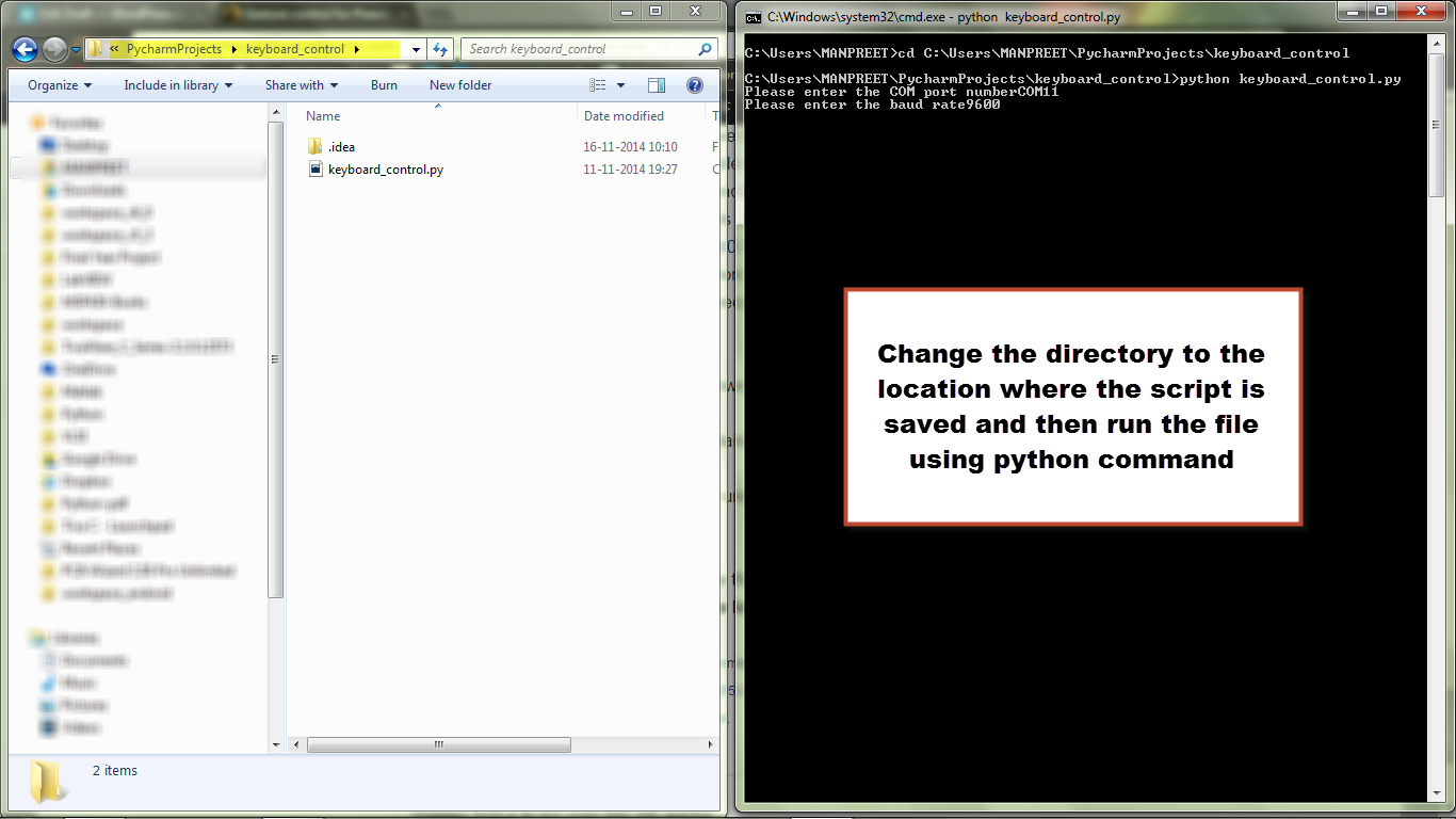
For running the python script install python 2.7. Copy paste the python script code into notepad and save it as gersturecontrol.py(or any name for that matter) Then follow these steps.

  1. Open command prompt(Press windows+r, then type cmd and press enter.)
  2. opening_command_prompt

  3. Change the directory to the one containing your python script i.e. the .py file. Use cd for that.
  4. file_location

  5. Use python gesturecontrol.py for running your code
  6. running the program

  7. For stopping the code press ctrl+c

Thank you for reading the post and hope that it was helpful.If you like the post do share it with others and spread the knowledge.

Wireless Notice Board using SIM 300 and EK-TM4C1294XL

Well I just loved the idea of a wireless noticeboard which will display the notice whenever some sms is sent to it. That way you can intimate the concerned people about the notice or information even if you are not physically present at the location. This can be used in colleges wherein two notice boards can be installed per department. One will be used by the principal and the other may be by the head of dept. or the teachers. This is a quick way to send the info. So starting with the list of materials required.

Components

  • Micro-controller board with at least two hardware UARTs(not mandatory but will be beneficial.)
  • SIM 300 module or equivalent(with the charger etc.)
  • Some display e.g. LCD, dot matrix, graphical LCD etc.

Connections

connections

EK-TM4C1294XL Pins

TM4C129-X11-—-Pins-Maps

Code Explanation

The main objective is to extract the message from the received message. Now you can use some special character for this but I’ve decided to use the concepts of html tags. So my tag is <s></s>. Whatever is written in these tags will be displayed. String object provides beautiful string manipulation functions. So we will not reinvent the wheel but use it in our application so to speak. Let’s look at the code that will extract the message from the received data.

  char buffer[250];
  Serial.readBytes(buffer, 250);
  String message = buffer;
  String command = "<s>";
  String commandEnd ="</s>";
  int indexOfMessage = message.indexOf(command);
  int indexOfMessageEnd = message.indexOf(commandEnd);
  if(indexOfMessage>0 && indexOfMessageEnd>0){
  String actualMessage = message.substring(indexOfMessage+3,indexOfMessageEnd);
  Serial.print("Message             :");
  Serial.println(message);
  Serial.print("Command             :");
  Serial.println(command);
  Serial.print("CommandEnd          :");
  Serial.println(commandEnd);
  Serial.print("Actual Message      :");
  Serial.println(actualMessage);
  actualMessage.toCharArray(actualMessageArray,250);

We are making two strings command and commandEnd. These will store our tags. Next we need to find the index of these tags. For this we use indexOf() and this will return –1 if the string is not present. So we need to send the message only if both the indices are not –1.Next is just one toCharArray(), this is for the LCD function. Also the serial printing is just for our reference. You may remove those lines.

The scrolling part is taken from arduino cook book. Here is the link.

Thank you for reading this. If you liked this post do share it with others!!

Entire Code

#include <LiquidCrystal.h>;
LiquidCrystal lcd(42,44,49,50,70, 69);

const int numRows = 2;
const int numCols = 16;
char actualMessageArray[250];

void setup()
{
	  // put your setup code here, to run once:
	  Serial.begin(9600);
	  Serial7.begin(9600);
	  Serial7.println("AT");
	  while(Serial.available()>0)
	  {
		Serial.print((char)Serial.read());
	  }
	  delay(1000);
	  Serial7.println("AT+CMGF=1");
	  while(Serial.available()>0)
	  {
		Serial.print((char)Serial.read());
	  }
	  delay(1000);
	  Serial7.println("AT+CNMI=2,2,0,0");
	  delay(100);
	  while(Serial.available()>0)
	  {
		Serial.print((char)Serial.read());
	  }
	  delay(1000);
	  lcd.begin(numCols, numRows);
	  lcd.setCursor(0,0);
}

void loop()
{
  // put your main code here, to run repeatedly:
 if(Serial.available()>0)
 {
	  char buffer[250];
	  Serial.readBytes(buffer, 250);
	  String message = buffer;
	  String command = "<s>";
	  String commandEnd = "</s>";
	  int indexOfMessage = message.indexOf(command);
	  int indexOfMessageEnd = message.indexOf(commandEnd);
	  if(indexOfMessage>0 && indexOfMessageEnd>0){
	  String actualMessage = message.substring(indexOfMessage+3,indexOfMessageEnd);
	  Serial.print("message          :");
	  Serial.println(message);
	  Serial.print("command          :");
	  Serial.println(command);
	  Serial.print("commandEnd       :");
	  Serial.println(commandEnd);
	  Serial.print("actualMessage    :");
	  Serial.println(actualMessage);
	  actualMessage.toCharArray(actualMessageArray,250);
	 }
 }
  marquee(actualMessageArray);
  delay(1000);
  lcd.clear();
}
void marquee( char *text)
{
	int length = strlen(text); // the number of characters in the text
	if(length < numCols)
	lcd.print(text);
	else
	{
		int pos;
		for( pos = 0; pos <= numCols; pos++)
		lcd.print(text[pos]);
		delay(1000); // allow time to read the first line before scrolling
		pos=1;
		while(pos <= length - numCols)
		{
		lcd.setCursor(0,0);
		for( int i=0; i < numCols; i++)
		lcd.print(text[pos+i]);
		delay(300);
		pos = pos + 1;
		}
	}
}

Serial Monitor Output

notice board

Video

SIM 300/900 (GSM Module)

INTRODUCTION

SIM 300 is a GSM modem with a simple serial interface. SIM 300 modem can accept any GSM network operator SIM card and act just like a mobile phone with its own unique phone number. With this module one can send/receive sms, connect to internet via GPRS and receive calls. The modem can either be connected to PC serial port directly or to any microcontroller. When purchasing purchase the entire board. As it comes with RS232 to TTL converter and ethernet port. Also do check the module by calling a few times when in the shop.

You can purchase this module online. Some of the sites are listed below:

  1. http://www.nskelectronics.com/sim300_modem_with_rs232.html
  2. http://robokart.com/wireless-modules/gsm-gprs/sim-900a-gsm-gprs-modem.html

SIM300_INTERFACE_MODULE_RS232_TTL-500x500

Fig.1 SIM300 Module

There are two LEDs on the board. One is power LED and the other is the network LED. When you insert your SIM card into the slot and power ON the device the power LED will be turned ON. After few seconds the network LED will start blinking after an interval of 3 seconds. If this happens it means signal is proper but if it is blinking faster it means that there is no network. If your mobile phone has network then this module should have network at the same location(provided the antenna is connected.) Make a call and it should ring. Do it a couple of times before purchasing from a store.

AT commands

These are the Haye’s command set also called AT commands. AT stands for attention. These commands are used to control the modem. Using these commands the modem can be operated. There are different commands for sending/reading sms etc. For further information about the history you can read the Wikipedia article.

The AT command set can be downloaded here.

at_commands

Above table lists few of the commands. The most basic command is AT and the response is OK. If you get OK then it means that everything is working fine.

exteneded_at

Now to test out the commands or for direct interfacing with the PC or laptop you can use USB to RS232 adapter.

USBRS232Cable_1

Fig. 2 USB to RS232 Adapter

You will need to install prolific drivers. These will be included in a small CD that accompanies the adapter or you can download here.

Once you do that there will be a COM port available now. Some of the basic commands are explained in the following video.