Embedded C programming using AVR Studio on Arduino Boards

For those of you who have an Arduino development board and wanted to code in embedded c and upload your code on the board, this is the right post.

For starters you need to download following components:
1. Arduino IDE Download Link
2. AVR Studio Download Link or AVRDUDE download

We shall be using AVRDUDE utility for burning our programs onto the micro-controller.

Once you’ve installed above programs. We can begin the setup of AVR studio using AVRDUDE for burning our programs.

First you must locate following two files:

  1.  avrdude.exe : If you have installed Arduino IDE then a sample path for this file is as follows. C:\Program Files (x86)\Arduino\hardware\tools\avr\bin\avrdude.exe
  2.  avrdude.conf : Similarly for Arduino IDE installation the path is as follows. C:\Program Files (x86)\Arduino\hardware\tools\avr\etc\avrdude.conf

If you are using AVRDUDE direct download, then these files shall be in the avrdude installation folder. example: C:\avrdude\avrdude.exe and C:\avrdude\avrdude.conf

We shall require both of these paths in the subsequent steps, so kindly ensure you’ve copied these two paths and kept it somewhere.

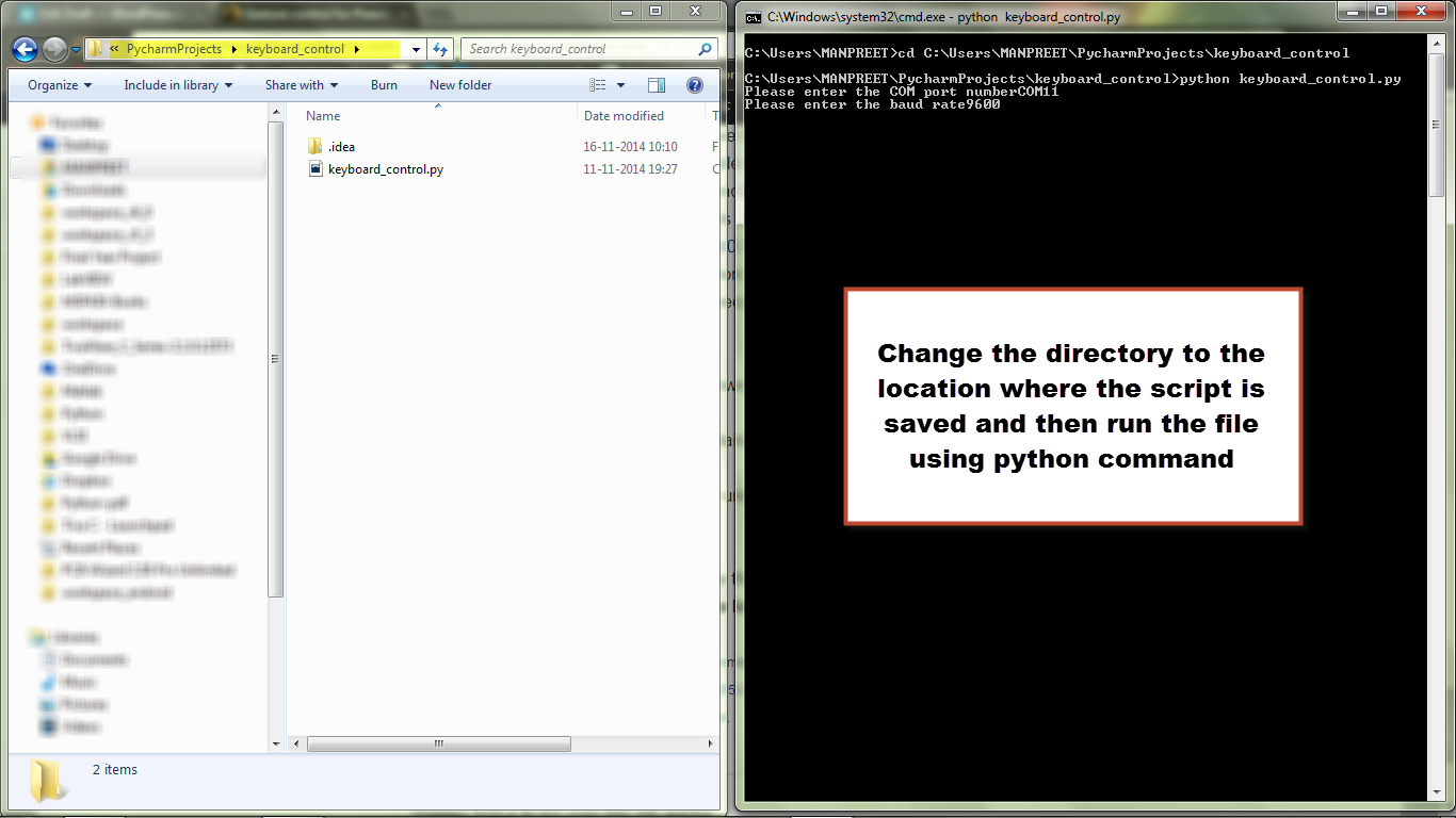
Next step is detecting which COM port your arduino board uses.

devicemanager

In my case the port used by the Arduino Board is COM3. Keep this information with you.

Now the AVRDUDE arguments is as follows:

  1. Arguments for Arduino Mega 2560
    -v -patmega2560 -cwiring -P COM3 -b115200 -D -Uflash:w:"$(ProjectDir)Debug\$(TargetName).hex":i -C"C:\avrdude\avrdude.conf"
  2. Arguments for Arduino UNO
    -v -patmega328p -carduino -P COM3 -b115200 -D -Uflash:w:"$(ProjectDir)Debug\$(TargetName).hex":i -C"C:\avrdude\avrdude.conf"

I shall explain few important command line options used in above commands. The detailed explanation for all the options is given in following documentation.
options
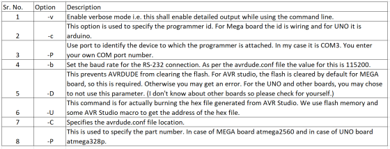
Now that we understand about the commands that shall be used, we can proceed with the creation of AVR Studio programmer.

avrstudioprogrammer

Steps:

  1. Open AVR Studio.
  2. Under tools select external tools.
  3. Press add.
  4. Name your programmer in the Title field.
  5. Paste the appropriate arguments in the Arguments field.
  6. Paste the avrdude.exe file path without the quotation marks in the Command field.
  7. Check the ‘Use Output window’ box.
  8. Press OK.

Now you have your programmer available in the tools menu above the external tools sub-menu.

You can upload a LED blinking program to your board to check whether everything is working.

Steps for testing

  1. Create a new GCC executable project
  2. Make your main.c file
  3. Build the project so that the hex file is generated
  4. Go to Arduino Programmer in the tools menu and click on it
  5. You should get an output window

If everything works you will have the hello world blinking LED.

Hope you liked the post. If you found it useful, please like and share! Remember sharing is caring 🙂

Gesture control for PowerPoint presentation

Basic idea of the project

The intention of this tutorial is to learn how to control computer keyboard and mouse events using your micro-controller. For demonstration I have chosen to name the project as gesture control for PowerPoint presentation. At the end of this tutorial you will be able to control the slides using your gestures. Now in order to control the operating system you need a language like python, java, c++ etc. I find python affable and powerful so I’ll be using that for coding. You can use any language you want but the logic and algorithm will remain the same, only the syntax will differ. I won’t be teaching you python in this post that is beyond the scope of this post. If you want to learn the language there is plethora of content available online. You just need a net connection and off you go.
P.S. : If you like the posts do like and share them with others.

Python

Python is an easy to learn high level programming language. It is a beautiful and a very powerful language. The packages that are available make it kind of limitless. Some of the places where python is used are mentioned below.

  • Google makes extensive use of Python in its web search systems.
  • The popular YouTube video sharing service is largely written in Python.
  • The Dropbox storage service codes both its server and desktop client software primarily in Python.
  • The Raspberry Pi single-board computer promotes Python as its educational language.
  • NASA, Los Alamos, Fermilab, JPL, and others use Python for scientific programming tasks.

So we know that most of the big shots use python. Now they use it for a reason and the reason being that its simply an awesome language. If you want to start learning programming you ought to start with python. Here are a list of sites and books that you may use for learning python.

  1. https://www.python.org/about/gettingstarted/ (This is the official page where you can learn how to install the IDE and get started.)
  2. Learning Python, 5th Edition (This is a good book if you are new to programming and otherwise as well.)
  3. http://www.learnpython.org/
  4. http://www.tutorialspoint.com/python/

Once you get the hang of it then you can directly use the documentations for learning how to use the packages.

pySerial and PyUserInput

We will be requiring these modules in our project. The names are quite self explanatory the former is for serial communication while the latter is for the mouse and keyboard events. The links to these modules are:

Well download these and install them. I recommend you to use 32bit python 2.7 version modules as well as the language. Because most of the modules are available for 2.7 version.

Components and Software requirements

  • A microcontroller board with UART capability e.g. MSP430G2 Launchpad, Arduino Uno board etc.
  • An accelerometer e.g. ADXL335 etc..
  • Python 2.7 , pySerial & PyUserInput modules

Connections

connections

I have used fritzing for making this. Here is the link to their home page.  http://fritzing.org/home/

Logic

We will calibrate the accelerometer and take readings for left and right position. Use the serial monitor for this. Read my tutorial titled Capacitive Accelerometer Interfacing if you don’t know what I am talking about. Next once you have those digital values you need to make the program for slide control. We know that left arrow and right arrow keys are used for navigation purpose. So in our python script the if statements will contain code for left arrow button press and right arrow button press. Note that you are reading the values that the controller is sending serially using python and taking decisions based on that value.

Energia Code

int x_pin = A0;
void setup()
{
  // put your setup code here, to run once:
  Serial.begin(9600);
  pinMode(x_pin,INPUT);
  analogReference(INTERNAL2V5);
}

void loop()
{
  // put your main code here, to run repeatedly:
  int x = analogRead(x_pin);
  Serial.println(x);
  delay(500);
}

Python Script

__author__ = 'MANPREET'
'''
This is a file for controlling keyboard events.
'''
from pykeyboard import PyKeyboard
import serial
import time

comPort = raw_input("Please enter the COM port number")
baudRate = raw_input("Please enter the baud rate")
myserial = serial.Serial(comPort, baudRate)
k = PyKeyboard()
TRUE = 1;
try:
    while (TRUE):
        if (myserial.inWaiting()):
            mydata = myserial.readline()
            x = int(mydata)
            print(x)
            if x > 650:
                k.tap_key(k.left_key)
                print("left")
                time.sleep(1)
            if x < 550:
                k.tap_key(k.right_key)
                print("right")
                time.sleep(1)
except KeyboardInterrupt:
    print("stop")

Code Explanation

The Energia code is pretty straightforward but still just to cover that as well. We have declared A0 i.e. P1.0 pin as input and changed the ADC reference voltage to 2.5V in line 7. Next part is just getting the ADC reading and sending it serially.

The python code demands some explanation. So lets begin understanding the code .

from pykeyboard import PyKeyboard
import serial
import time

This code will import three modules PyKeyboard, serial and time. For the pykeyboard we have imported the constructor. Then you have made one object k using the same.

comPort = raw_input("Please enter the COM port number")
baudRate = raw_input("Please enter the baud rate")
myserial = serial.Serial(comPort, baudRate)
k = PyKeyboard()

myserial is an object of the serial module that you have imported. You will use this to access its functions. The raw_input() is for taking the com port and baud rate values from the user. Example COM11 and 9600.

TRUE = 1;
try:
    while (TRUE):
        if (myserial.inWaiting()):
            mydata = myserial.readline()
            x = int(mydata)
            print(x)
            if x > 650:
                k.tap_key(k.left_key)
                print("left")
                time.sleep(1)
            if x < 550:
                k.tap_key(k.right_key)
                print("right")
                time.sleep(1)
except KeyboardInterrupt:
    print("stop")

Well this is an infinite loop and you are checking this block for keyboard interrupt i.e. ctrl+c . This is done so that you can come out of the program properly without having to kill the program. Next we are checking if there is data in the serial buffer. If yes then we are storing it in mydata variable. Convert it into integer and store it as some variable say x. Next step is easy write two if statements and include the code and condition for left arrow button press and right arrow button press. For more details of the PyKeyboard module visit : https://pypi.python.org/pypi/PyUserInput/0.1.9
For running the python script install python 2.7. Copy paste the python script code into notepad and save it as gersturecontrol.py(or any name for that matter) Then follow these steps.

  1. Open command prompt(Press windows+r, then type cmd and press enter.)
  2. opening_command_prompt

  3. Change the directory to the one containing your python script i.e. the .py file. Use cd for that.
  4. file_location

  5. Use python gesturecontrol.py for running your code
  6. running the program

  7. For stopping the code press ctrl+c

Thank you for reading the post and hope that it was helpful.If you like the post do share it with others and spread the knowledge.

Wireless Notice Board using SIM 300 and EK-TM4C1294XL

Well I just loved the idea of a wireless noticeboard which will display the notice whenever some sms is sent to it. That way you can intimate the concerned people about the notice or information even if you are not physically present at the location. This can be used in colleges wherein two notice boards can be installed per department. One will be used by the principal and the other may be by the head of dept. or the teachers. This is a quick way to send the info. So starting with the list of materials required.

Components

  • Micro-controller board with at least two hardware UARTs(not mandatory but will be beneficial.)
  • SIM 300 module or equivalent(with the charger etc.)
  • Some display e.g. LCD, dot matrix, graphical LCD etc.

Connections

connections

EK-TM4C1294XL Pins

TM4C129-X11-—-Pins-Maps

Code Explanation

The main objective is to extract the message from the received message. Now you can use some special character for this but I’ve decided to use the concepts of html tags. So my tag is <s></s>. Whatever is written in these tags will be displayed. String object provides beautiful string manipulation functions. So we will not reinvent the wheel but use it in our application so to speak. Let’s look at the code that will extract the message from the received data.

  char buffer[250];
  Serial.readBytes(buffer, 250);
  String message = buffer;
  String command = "<s>";
  String commandEnd ="</s>";
  int indexOfMessage = message.indexOf(command);
  int indexOfMessageEnd = message.indexOf(commandEnd);
  if(indexOfMessage>0 && indexOfMessageEnd>0){
  String actualMessage = message.substring(indexOfMessage+3,indexOfMessageEnd);
  Serial.print("Message             :");
  Serial.println(message);
  Serial.print("Command             :");
  Serial.println(command);
  Serial.print("CommandEnd          :");
  Serial.println(commandEnd);
  Serial.print("Actual Message      :");
  Serial.println(actualMessage);
  actualMessage.toCharArray(actualMessageArray,250);

We are making two strings command and commandEnd. These will store our tags. Next we need to find the index of these tags. For this we use indexOf() and this will return –1 if the string is not present. So we need to send the message only if both the indices are not –1.Next is just one toCharArray(), this is for the LCD function. Also the serial printing is just for our reference. You may remove those lines.

The scrolling part is taken from arduino cook book. Here is the link.

Thank you for reading this. If you liked this post do share it with others!!

Entire Code

#include <LiquidCrystal.h>;
LiquidCrystal lcd(42,44,49,50,70, 69);

const int numRows = 2;
const int numCols = 16;
char actualMessageArray[250];

void setup()
{
	  // put your setup code here, to run once:
	  Serial.begin(9600);
	  Serial7.begin(9600);
	  Serial7.println("AT");
	  while(Serial.available()>0)
	  {
		Serial.print((char)Serial.read());
	  }
	  delay(1000);
	  Serial7.println("AT+CMGF=1");
	  while(Serial.available()>0)
	  {
		Serial.print((char)Serial.read());
	  }
	  delay(1000);
	  Serial7.println("AT+CNMI=2,2,0,0");
	  delay(100);
	  while(Serial.available()>0)
	  {
		Serial.print((char)Serial.read());
	  }
	  delay(1000);
	  lcd.begin(numCols, numRows);
	  lcd.setCursor(0,0);
}

void loop()
{
  // put your main code here, to run repeatedly:
 if(Serial.available()>0)
 {
	  char buffer[250];
	  Serial.readBytes(buffer, 250);
	  String message = buffer;
	  String command = "<s>";
	  String commandEnd = "</s>";
	  int indexOfMessage = message.indexOf(command);
	  int indexOfMessageEnd = message.indexOf(commandEnd);
	  if(indexOfMessage>0 && indexOfMessageEnd>0){
	  String actualMessage = message.substring(indexOfMessage+3,indexOfMessageEnd);
	  Serial.print("message          :");
	  Serial.println(message);
	  Serial.print("command          :");
	  Serial.println(command);
	  Serial.print("commandEnd       :");
	  Serial.println(commandEnd);
	  Serial.print("actualMessage    :");
	  Serial.println(actualMessage);
	  actualMessage.toCharArray(actualMessageArray,250);
	 }
 }
  marquee(actualMessageArray);
  delay(1000);
  lcd.clear();
}
void marquee( char *text)
{
	int length = strlen(text); // the number of characters in the text
	if(length < numCols)
	lcd.print(text);
	else
	{
		int pos;
		for( pos = 0; pos <= numCols; pos++)
		lcd.print(text[pos]);
		delay(1000); // allow time to read the first line before scrolling
		pos=1;
		while(pos <= length - numCols)
		{
		lcd.setCursor(0,0);
		for( int i=0; i < numCols; i++)
		lcd.print(text[pos+i]);
		delay(300);
		pos = pos + 1;
		}
	}
}

Serial Monitor Output

notice board

Video

Capacitive Accelerometer Interfacing

Well in this post I’ll be telling briefly what is an accelerometer and how to interface it with a microcontroller. To be honest I woke up in the middle of the night and couldn’t go back to sleep, so I decided to write this post which I was planning on writing for some time now.

Accelerometer

It is basically a device which is used for measuring acceleration or change in motion. You use one more often than you know. There is an inbuilt accelerometer in your cellular mobile phones and tablets. So now you know what is used for detecting the tilts in your phone. Next time you play temple run or similar game you would know that all this fun is possible due to a technology called accelerometer and other stuff. Then modern laptop hard disks have accelerometers to detect fall. If fall is detected the writing head in retraced so that the disk is not damages and there are no scratches. There are numerous other applications and examples. I just gave food for thought you can explore the rest on your own.

Types of Accelerometer

Well as you may have already guessed there are various types of accelerometers.

  • Capacitive Accelerometer
  • Magneto-resistive Accelerometer
  • Piezo-electric Accelerometer

There are various other types these three being examples.This is a video one of my instructors showed me. The guy explains the working and construction quite well.

This is an article having good information about accelerometers

http://www.engineersgarage.com/articles/accelerometer?page=1

Data from accelerometers

Now that you know how accelerometers work. Let’s come to the topic at hand i.e. using one with your microcontroller.

Well there are different types of accelerometers depending on the type and method of obtaining data. While the data acquisition may be different but processing part is same once you get the reading. So the data may be available as an analog signal or may be it may be available inside the accelerometer in a register which you need to access via a protocol like SPI etc..

ADXL 335

So I’ll be talking about this accelerometer. You can look at the datasheet before deciding to use it.

So this accelerometer gives the output as three analog signals. There are three pins x,y,z for the three axes. Then there is Vcc and GND.

For actually using this signals you need to convert them into digital form. For this you use the inbuilt 12bit ADC that is available in msp430g2553.(If your controller does not have an inbuilt ADC, which won’t be the case, you can use an external ADC or if your application requires faster conversion and better precision and stability then you can use external ADC.) So once you have the data in digital form, next step would be calibration of the accelerometer.

Calibration

Now you have the data in digital form but what to do with it and how to see it? The answer is you send the digital reading serially and observe it on a serial monitor. So you make variables and store the digital reading in those and view the numbers on screen. Now you will make a table for these variables and decide the limits. Suppose you want to detect forward tilt, you can note what are the range of values that the accelerometer gives for the gesture and the using a simple if statement write whatever you want your application to do on a forward tilt.

Position Digital Range of X Digital Range of Y
Forward N.A <658
Backward N.A >705
Left >497 N.A
Right <460 N.A
Stop 470 to 485 695 to 705


The above code is an example of finding the ranges. You can then use basic if else for this. If you want a video showing the calibration process do tell me.

Code for gesture controlled bot

void setup()
{
  pinMode(P2_0,OUTPUT);
  pinMode(P2_1,OUTPUT);
  pinMode(P2_2,OUTPUT);
  pinMode(P2_3,OUTPUT);
  pinMode(A0,INPUT);//X
  pinMode(A3,INPUT);//Y
  pinMode(P1_4,INPUT);
  //pinMode(A2,INPUT);//Z
  Serial.begin(9600);
  Serial.println("Start");
}
void loop()
{
  int x = analogRead(A0);
  int y = analogRead(A3);
  int m = digitalRead(P1_4);
  //Serial.print(x);
  //Serial.print(','); //use these lines for calliberation
  //Serial.println(y);
   if(y>520)
  {
  digitalWrite(P2_0,HIGH);
  digitalWrite(P2_1,LOW);
  digitalWrite(P2_2,HIGH);
  digitalWrite(P2_3,LOW);
  Serial.println("BACKWARD");
  //delay(100);
  }
  if(y<460)
  {
  digitalWrite(P2_0,LOW);
  digitalWrite(P2_1,HIGH);
  digitalWrite(P2_2,LOW);
  digitalWrite(P2_3,HIGH);
  Serial.println("FORWARD");
  //delay(100);
  }
  if(x>445)
  {
  digitalWrite(P2_0,LOW);
  digitalWrite(P2_1,LOW);
  digitalWrite(P2_2,LOW);
  digitalWrite(P2_3,HIGH);
  Serial.println("LEFT");
  //delay(100);
  }
  if(x<430)
  {
  digitalWrite(P2_0,LOW);
  digitalWrite(P2_1,HIGH);
  digitalWrite(P2_2,LOW);
  digitalWrite(P2_3,LOW);
  Serial.println("RIGHT");
 // delay(100);
  }
  if(x>430 && x< 445 && y>460 && y<500)
  {
  digitalWrite(P2_0,LOW);
  digitalWrite(P2_1,LOW);
  digitalWrite(P2_2,LOW);
  digitalWrite(P2_3,LOW);
  Serial.println("STOP");
  //delay(100);
  }  
}

(If you would like the embedded c code email me.)

P.S.

If you like my articles do like them. Well just want to say a little appreciation goes a long way. Thank you for reading the post.

Energia + MSP430 = Arduino!!! in PDIP :D


EnergiaHello everyone. This post is regarding an IDE called Energia, for msp430 launchpad. There are millions of arduino fans out there, who love the inbuilt libraries and functions for making projects easily. Hobbyists have the natural tendency to use arduino for their projects. This is justified by the large number of  *shields that are available for arduino and the awesome arduino community.  This is a good news for them as Energia enables coding msp430 microcontrollers using the arduino libraries and functions. In fact Energia has inbuilt example ‘sketches’ just like the arduino IDE which you can build and burn in the controller.

energia-ide

Yes the blink led sketch and all others, you can directly set the microcontroller you want to use and get the fun started. Energia is an open source project just like arduino. It was launched in 2012 i.e last year. There have been a few updated to improve the stability. The color of Energia is red (launchpad!!) unlike arduino which is blue. Now to talk about the code efficiency and the IDE stability. Since it uses another processors IDE libraries and functions and converts it into those which are compatible with our launchpad controllers, it is slower as compared to CSS,IAR and other development environments. It may seem to test your patience, but then you are getting best of both worlds right? So one shouldn’t complain about it. So now you have various methods to reduce your coding time. If you want to interface an 16x2LCD just import the lcd library and use the inbuilt functions to perform the tasks that you require. So if a LCD is like ABCD.. type basic thing in your project you can avoid initializing those peripherals manually via control signals and command words. Makes our life easy, isn’t it?

This is the link to the Energia website if you are interested.

http://www.energia.nu

Here you can download the latest Energia version. There is help page as most sites have. The most important advantage of Energia is that you’ll open up the gate to a humongous community i.e arduino community.

Hope this post was informative. Thank you for reading this.

* Shield refers to a hardware that performs a specific set of tasks and can be mounted onto the arduino board. On that note I’ll like to introduce the booster packs of launchpad. Booster pack is the launchpad version of the name shield.